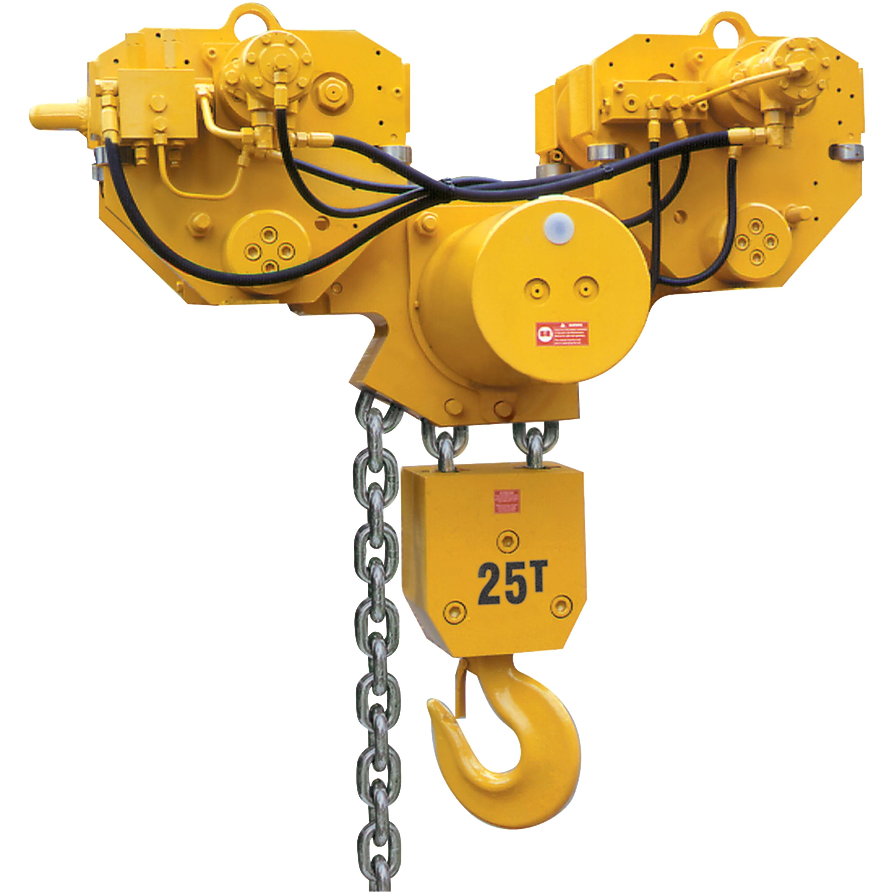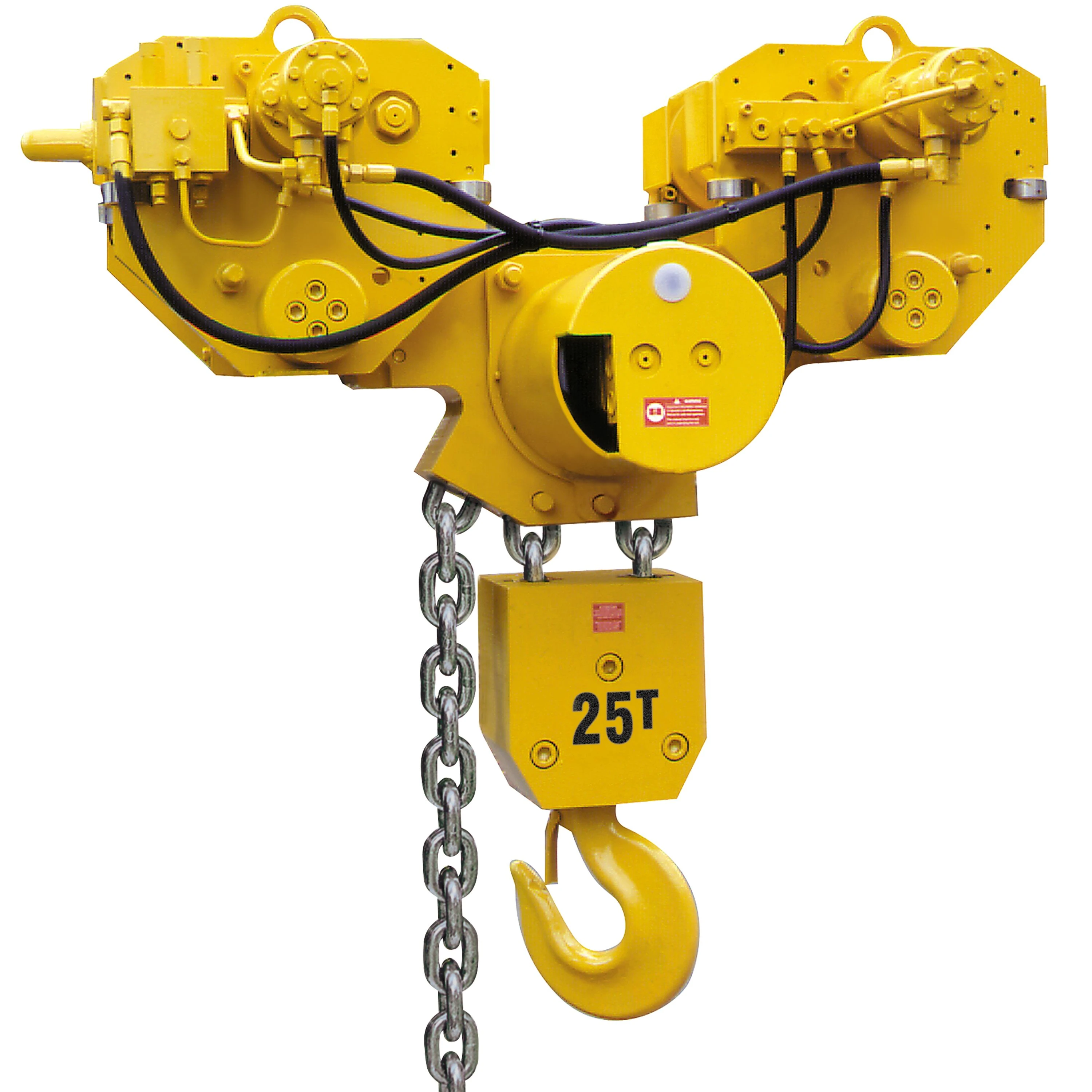
BS Gear Motor Series - Hoist Sub-Assembly

Model

BS25LC2H2

BS30LC2H3

BS36LC2H3

BS40LC2H4

BS50LC2H4

BS50LC2H2

BS75LC2H3

BS100LC2H4

BS125LC2H5

BS150LC2H6

BS150LCH3

BS200LCH4

Capacity(metric tons)

25

30

36

40

50

50

75

100

125

150

150

200

Falls of load chainper hoist

2

3

3

4

4

2

3

4

5

6

3

4

Min. headroom(in)

44.7

47.6

47.6

48.8

48.8

41.1

46.9

48.5

54.5

59.8

73.4

77.2

Lifting speed at rated load(fpm)

6.2

4.1

4.1

3.6

3.6

7.4

4.9

3.6

3.0

2.5

1.6

1.1

Lifting speed at no load(fpm)

6.2

4.1

4.1

3.6

3.6

7.4

4.9

3.6

3.0

2.5

1.6

1.1

Lowering speed at rated load(fpm)

6.2

4.1

4.1

3.6

3.6

7.4

4.9

3.6

3.0

2.5

1.6

1.1

Working pressure(PSI)

1813

2103

2103

2103

2103

2538

2610

2683

2755

2828

2175

2610

Calibration pressure(PSI)

2465

2538

2538

2538

2538

3045

3045

3045

3190

3190

3045

3045

Nominal flow(gpm)

11

11

11

11

11

13

13

13

13

13

11

13

System weight(lbs)

2208

3753

3753

4084

4084

6843

8609

9051

13024

13907

28256

28918

Chain size(mm)

16x45

16x45

16x45

16x45

16x45

22x66

22x66

22x66

22x66

22x66

32x90

32x90

BS Gear Motor Series - Trolley Sub-Assembly


Model

BS25LC2A2

BS30LC2A3

BS36LC2A3

BS40LC2A4

BS50LC2A4

BS50LC2A2

BS75LC2A3

BS100LC2A4

BS125LC2A5

BS150LC2A6

BS150LCA3

BS200LCA4

Number of wheels per hoist

4

4

4

4

4

8

8

8

8

8

16

16

Std Flange adjustment(in)

6,3-12,4

6,3-12,4

6,3-12,4

6,3-12,4

6,3-12,4

6,3-12,4

6,3-12,4

6,3-12,4

6,3-14,2

6,3-14,2

6,1-12,4

7-12,4

Max beam bottom flange thickness(in)

1.6

1.6

1.6

1.6

1.6

1.6

1.6

1.6

4

4

1.6

1.6

Wheel tread diameter(in)

6.3

8.9

8.9

8.9

8.9

6.3

8.9

8.9

9.8

9.8

8.9

8.9

Wheel loading per pair(lbs)

13797

16556

19868

27594

27594

13797

20695

27594

34492

41391

20695

27594

Trolley Assy length(in)

24.5

30.8

30.8

30.8

30.8

55.6

66.6

66.6

81.1

81.1

133.6

133.6

Number of motors per trolley

1

1

1

1

1

2

2

2

2

2

4

4

Trolley air cons. Per hoist(scfm)

67

67

67

67

67

134

134

134

134

134

268

268

Max travelling speed at rated load(fpm)

39

49

49

39

39

39

39

39

30

30

33

33

BHS Piston Motor Series - Trolley Sub-Assembly


Model

BHS50LC2A2

BHS75LC2A3

BHS100LC2A4

BHS125LC2A5

BHS150LC2A6


Number of wheels per hoist

8

8

8

8

8


Std Flange adjustment(in)

6.3 - 12.4

6.3 - 12.4

6.3 - 12.4

6.3 - 14.2

6.3 - 14.2


Max beam bottom flange thickness(in)

1.6

1.6

1.6

4

4


Wheel tread diameter(in)

6.3

8.9

8.9

9.8

9.8


Wheel loading per pair(lbs)

13797

20695

27594

34492

41391


Trolley Assy length(in)

55.6

66.6

66.6

81.1

81.1


Number of motors per trolley

1

1

1

1

1


Trolley air cons. Per hoist(scfm)

49

49

49

49

49


Max travelling speed at rated load(fpm)

39

39

39

30

30


Using the right trolley size is crucial for your installation.

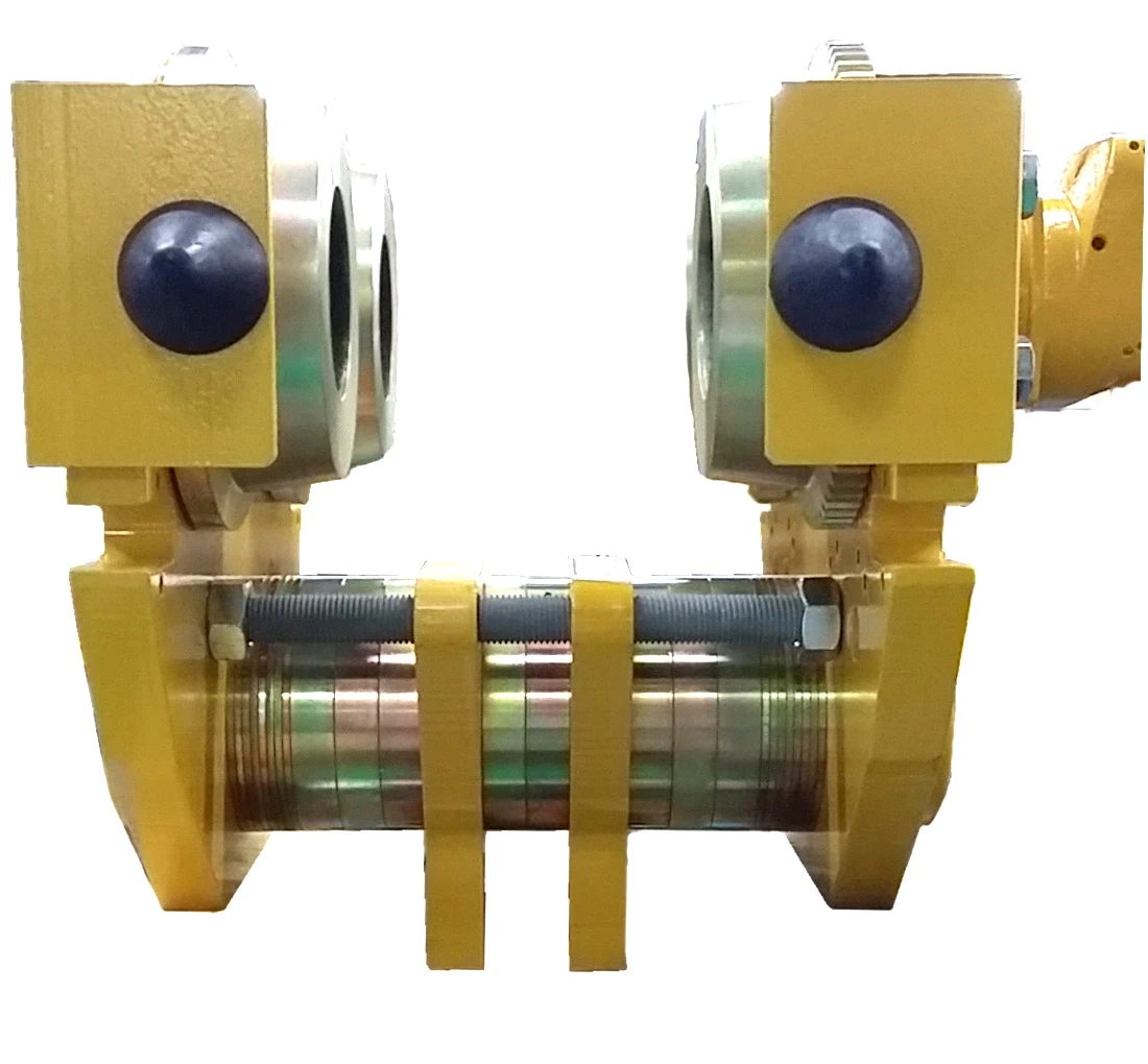
Ingersoll Rand has created two trolley sizes in order to match any configuration, even with large structural beams, for any specific situation.

PTL-En-Product-Chart-liftchain-air-bop
PTL-En-Product-Chart-liftchain-air-bop-V2

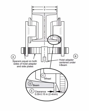
Flange adjustment: X = Y + 2 * E

To select the correct trolley size, you need to check if your theoretical beam size "Y" plus the clearance "E" on each side of the beam is compatible with the flange adjustment range "X" shown in the standard Model Specifications tables. 

For very large beams, an optional wide beam flange adjustment (option "W") can be ordered. Please contact your Ingersoll Rand representative to order. 

Series

Capacity (metric ton)

Flange Adjustment "X" (mm)


Maximum Bottom Flange Thickness (mm)

Standard

Wide (option "W")


BS

25

130 - 314

315 - 410

40

BS

25 / 30 / 36 / 40 / 50 (4 falls)

140 - 314

315 - 410

40

BS / BHS

50 (2 falls) / 75 / 100

160 - 314

315 - 410

40

BS / BHS

125 / 150 (6 falls)

160 - 360

365 - 410

102

BS

150 (3 falls) / 200

170 - 314

315 - 410

40

LBS

24.0

140 - 314

315 - 410

40

LBS

36 / 50

170 - 314

315 - 410

40

ULBS

100

270 - 314

315 - 410

40

ULBS

150 / 200

200 - 314

315 - 410

40

ULBS

250

200 - 360

365 - 410

102

Controls

When the BOP system has to be installed on a bi-directional bridge crane, the PHS6 pendant allows full control of the 3 movements. The progressive control levers provide an exceptional variable speed control of the load. Various versions are available to meet CE and ATEX requirements.

PTL-En-Product-Photo-liftchain-air-bop-V1
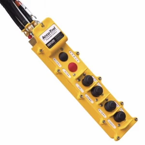
PHS6E-U Pendant, CE Version

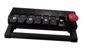
The Accu-trol™ pendant is an alternative to the standard PHS pendant, offering a vertical arrangement of the control buttons in a fully enclosed impact resistant frame. Available with up to three functions (6 motions), and optional emergency stop button with CE version.

PTL-En-Product-Photo-liftchain-air-bop-V2
Accu-trol Pendant, Non-CE Version

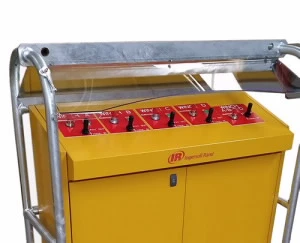
Ingersoll Rand can also offer a standing control console for remote control of 2 or more hoists. From the instrument panel, each hoist can be run individually and an additional joystick allows the operator to simultaneously control a group of hoists. Emergency stop buttons are fitted as standard on CE versions

PTL-En-Product-Photo-liftchain-air-bop-V3
Control Console for Four Hoists, CE Version

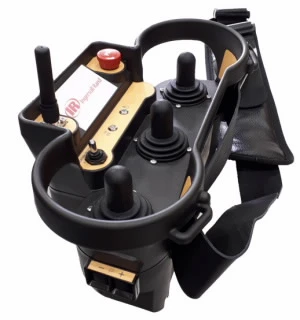
Ingersoll Rand has delivered many wireless control systems to customers with specific features to match their applications. 

  • 2 or 4 hoists control
  • ATEX certified
  • Simultaneous control
  • Real load display
PTL-En-Product-Photo-liftchain-air-bop-V4
Wireless Controller

Air Supply


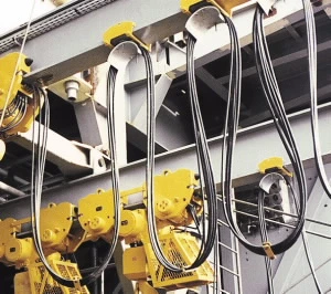
Air hose kits of different sizes and lengths can be ordered with your hoists system to create a supply line. The kit includes the high quality hose and end fittings to connect to the hoist inlet and the supply source.

Festooning trolleys will support the air hose on the travelling beam; number of trolleys has to be determined with your Ingersoll rand representative depending on the travel length and the loop height.
Specific models are available for ATEX zone 1 areas.

PTL-En-Product-Photo-liftchain-air-bop-V5

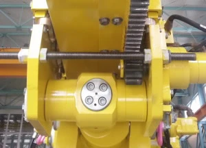
Rack & Pinion Drive

When harsh conditions are met in offshore operations, our Rack & Pinion drive system offers a positive engagement. Rack sections of 1.5 meters long have to be welded on the travel beam. The positioning underneath the beam flange prevents dust contamination and ensures long life.

PTL-En-Product-Photo-liftchain-air-bop-V6

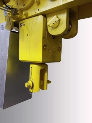
Retention Lug

This additional hanging point on the hoist trolley assembly allows for suspending the BOP stack for storage. While using the retention lug, the hoist drive and brake mechanism are not subject to vibrations under load tension. Light maintenance operations can also be performed on the hoist while the BOP is secured using this lug.

PTL-En-Product-Photo-liftchain-air-bop-V7